GD&T: Measurement Discrepancies in CMM when using a Holding Fixture –
It Passes And Then It Fails?
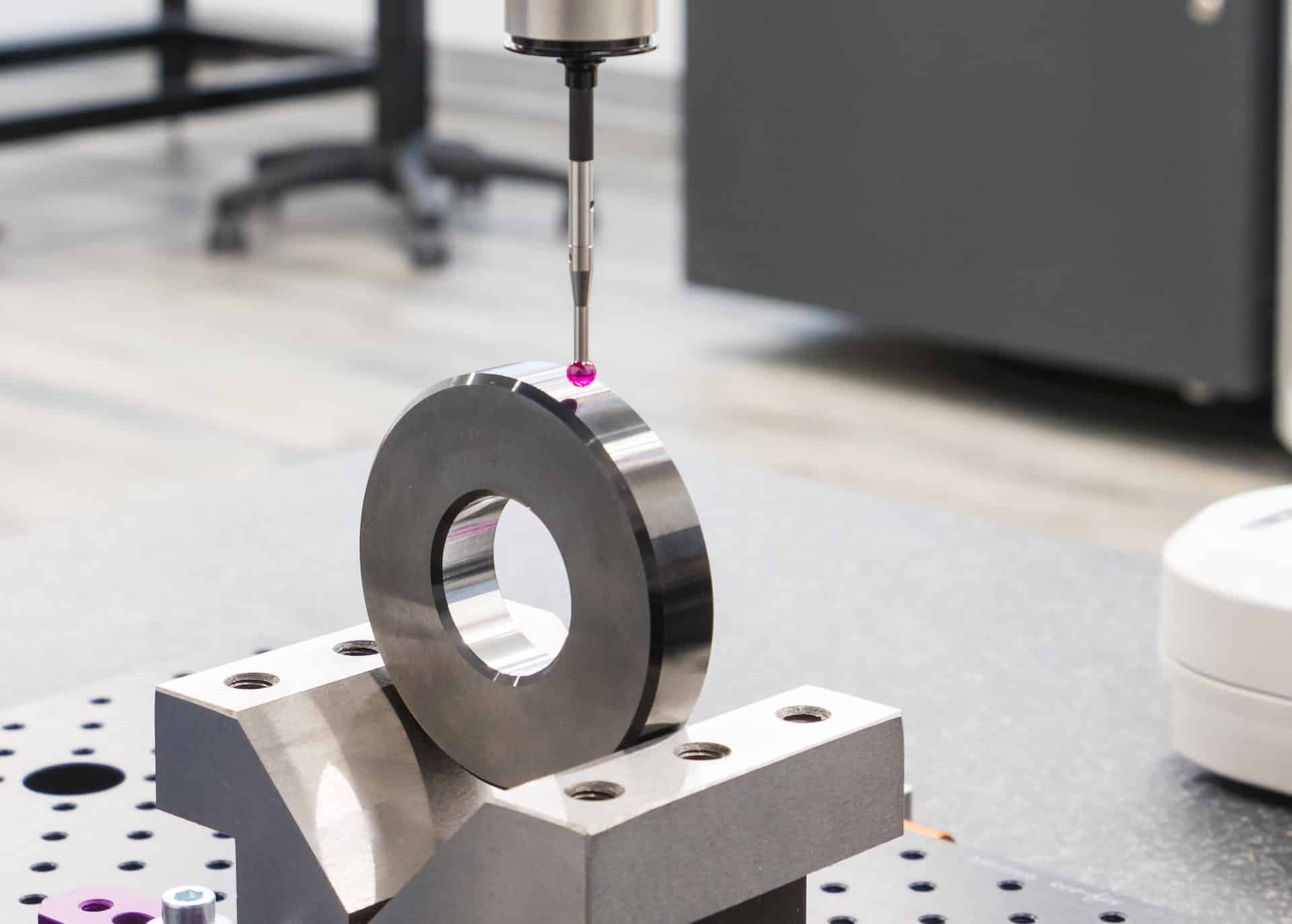
I received a phone call from a quality manager who was one of my previous GD&T students. He asked me, “Why am I getting passing results when I measure hole locations on our coordinate measuring machine (CMM), but when I check the features of the same part on a functional gage, it doesn’t fit?” There are a couple of possible reasons as to why he was getting different outcomes when applying his two different measuring methods on the same part. Actually, there are even more possibilities for variation when you consider some of the methods that come into play when performing measurement systems analysis or capability studies, but that is a topic for a different time. What we will concentrate on here is differing results that are obtained by directly probing surface points on a part surface using a coordinate measurement machine (CMM) and indirectly probing points that represent that same surface using a holding fixture gage. It should be first noted that a functional gage used by the manager mentioned above is not the same as a holding fixture gage. A functional gage is a go/no-go gage that checks features from datums on the gage to actual feature(s) such as hole locations. A holding fixture gage is an accurately-made fixture that is used in combination with the CMM to establish the datum features on the part. There are more nuances to each of these gages, but this description should suffice for the purposes of this article. When a CMM operator is probing points on features such as datum surfaces, the points obtained should represent the worst-case points, or the farthest points protruding from the surface. The more points that the operator probes on any given surface, the better chance he has to obtain those needed extreme points. If the operator doesn’t hit the highest points, the datum that is created by the CMM doesn’t really represent the actual extreme edge of the surface. Have a look at the diagram below. Part of the left surface of part actually goes beyond the surface (tertiary datum) that was created by the CMM because points were not probed in that area. The perpendicularity/flatness variation of that surface (to the secondary datum) will contribute to the error of the tertiary datum. Usually, the primary datum in this example isn’t much affected because the operator will probe the surface plate that the part rests on and not the primary datum feature of the part itself (although the primary datum could be on the top of the part, and thus the same error could occur on it as well). The datum reference framework that is created by probing the surfaces of the part using the CMM is called the Theoretical Datum Reference Frame.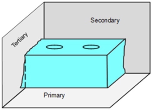 A way to better achieve a true representation of the surface is to start out with a physical Datum Reference Frame (sometimes called a corner fixture or Datum Simulator). The CMM operator probes points on physical inspection equipment that is constructed as three mutually perpendicular planes. This is the preferred measurement setup in many, if not most, scenarios because the inspection equipment is in contact with the high points of the part. This is called the Physical Datum Reference Frame.
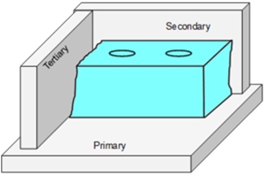 As you can see, the distance from the tertiary datum feature to the measured features (holes in this example) will vary in the “X” direction by the amount of the perpendicularity error that exists between the tertiary datum to the higher-ranking secondary datum feature. The same error concept as described above applies to the distance to the holes from the secondary datum feature in the “Y” direction.
The tolerances for a holding fixture like this should follow a 10:1 rule normally followed in the manufacturing industry. For example, if the distance from the datum surface to the hole(s) has a total locational tolerance of .010” (both directions), the perpendicularity of all of the datum surfaces should be .001” maximum.
If you don’t have access to a nice holding fixture like this and you need to probe according to the first diagram, make sure you probe a sufficient number of points to construct that datum surface(s). On your CMM, when defining the plane, it will present you with the option to construct a best-fit, or regression plane of the probed points, a min plane or a max plane. Choose the max plane (maybe your CMM software uses the term, “tangent plane” for the max plane). This will more closely replicate the actual extreme surface of the part. You have three planes to construct and to converge (intersect), so remember that this concept applies to all three perpendicular planes. Also, not knowing your specific CMM terminology or its underlying algorithms, there may be more steps for you to consider to ensure that all three datums are simulated correctly.
In this article, we have only addressed datum surfaces. We haven’t taken into consideration the Y14.5 standard-prescribed methods for probing and measuring the locations of the holes. This has its own nuances and complications. This aspect will be saved for another time!
So, “What is the conclusion of the whole matter?” as the wise king asks in the book of Ecclesiastes? When possible, probe your CMM points on an accurately-made datum feature simulator like the one represented in the second diagram or, as depicted in the first diagram, carefully probe a sufficient number of points on the datum feature surface itself, choosing the max surface. The accuracy of the location of the holes depends on it!
Questions or comments? Contact us here.
Dan Medford
Author of Fundamentals of Geometric Dimensioning and Tolerancing, 3rd ed., 2018
As you can see, the distance from the tertiary datum feature to the measured features (holes in this example) will vary in the “X” direction by the amount of the perpendicularity error that exists between the tertiary datum to the higher-ranking secondary datum feature. The same error concept as described above applies to the distance to the holes from the secondary datum feature in the “Y” direction.
The tolerances for a holding fixture like this should follow a 10:1 rule normally followed in the manufacturing industry. For example, if the distance from the datum surface to the hole(s) has a total locational tolerance of .010” (both directions), the perpendicularity of all of the datum surfaces should be .001” maximum.
If you don’t have access to a nice holding fixture like this and you need to probe according to the first diagram, make sure you probe a sufficient number of points to construct that datum surface(s). On your CMM, when defining the plane, it will present you with the option to construct a best-fit, or regression plane of the probed points, a min plane or a max plane. Choose the max plane (maybe your CMM software uses the term, “tangent plane” for the max plane). This will more closely replicate the actual extreme surface of the part. You have three planes to construct and to converge (intersect), so remember that this concept applies to all three perpendicular planes. Also, not knowing your specific CMM terminology or its underlying algorithms, there may be more steps for you to consider to ensure that all three datums are simulated correctly.
In this article, we have only addressed datum surfaces. We haven’t taken into consideration the Y14.5 standard-prescribed methods for probing and measuring the locations of the holes. This has its own nuances and complications. This aspect will be saved for another time!
So, “What is the conclusion of the whole matter?” as the wise king asks in the book of Ecclesiastes? When possible, probe your CMM points on an accurately-made datum feature simulator like the one represented in the second diagram or, as depicted in the first diagram, carefully probe a sufficient number of points on the datum feature surface itself, choosing the max surface. The accuracy of the location of the holes depends on it!
Questions or comments? Contact us here.
Dan Medford
Author of Fundamentals of Geometric Dimensioning and Tolerancing, 3rd ed., 2018